

This was something I wanted to do, but kept putting it off for a while as I wasn’t quite sure that I knew everything that I needed to know for the install. The biggest thing here is fear of the unknown. It’s not that hard to do, but it is scary to cut your wiring harness. At least it was for me. It is important to note that the LC-1 can be installed in different places. My information here is for installing it in stock O2 Sensor location 1 (Passenger side in header). The wiring will be a little different if you install into location 2 or if you have the bung installed and put it there.
I got the majority of my info from reading posts on the board from people like Tem. I got even more information from beanie and rando. Rando helped out with the “which wire goes where questions” and beanie helped out with the FC-Edit and DataLogit parts as well as helping me muster the courage to attempt this. So let me describe my installation process. Hopefully, this will be helpful as to you as it was to me once I gathered all the data.
Tools Needed:
o 10MM socket for storage bin pieces
o O2 Sensor socket
o ?? socket/wrench to disconnect battery terminals
o Wire cutters
o Wire strippers
o Eye Connectors for wires (Helps with connecting to ground)
o Soldering iron
o Solder
o Hair Dryer or heat gun
o Shrink tubing
o Drill and/or knife
o In-line fuze holder
o 5 Amp fuze to go in holder.
o Small guage wire (It helps to have some different colors to choose from). I happen to have a lot of wire around the house.
o Small flat head screw driver
o Zip Ties
o Adhesive velcro
o A friend to help you would be a good idea too.
Naming Conventions I use here:
o Left side = Driver’s side
o Right side = Passenger side
o FC-Box = DataLogit box
o PFC = PowerFC unit
o ECU = the brains of the car. The thing you’re replacing with the PFC.
o LC-1 = actual LC-1 Controller and its attached wires. Not the Sensor.
o WB Sensor = The WB 02 sensor that plugs into the LC-1 controller.
o Copilot = The greatest software ever written for use with the MR2 Spyder.
OK. First you need to take a breath and make sure you have all the stuff you need so you’re not running back and forth during the installation. Once you’re ready, follow these steps.
1. Disconnect the both battery terminals. Now remove the battery and plastic holding tray from the car and set it aside. *NOTE* Do NOT set the battery down on concrete. Look down towards the firewall and you’ll notice 2 big rubber grommets that have a lot of wires going in them. You will later be drilling a hole in the side of the lower grommet.
2. Next, take the Storage bin doors off with the 10MM socket. Next take off the left side storage bin plastic pieces. There are 2 of them. 1 is on the side that has a couple “push-pull” clips that hold it in. Simply pull on those and take that out. The next piece is the bottom piece. This is held in by 2x 10MM bolts and sort of interlocks to the right side bottom piece. Take out the 2 bolts and wiggle it free from the right side piece.
Here is where you’ll mount the PFC:
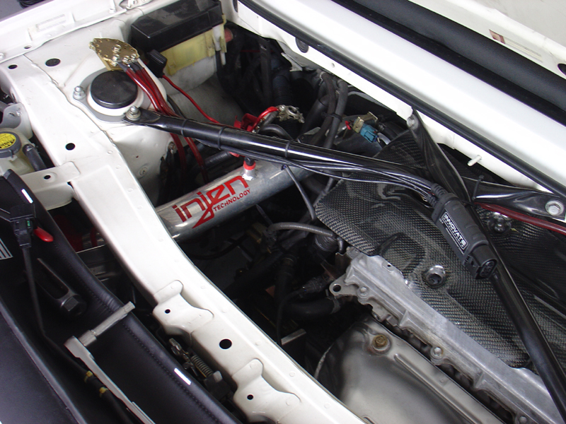
3. Locate Where you are going to mount the LC-1. I chose to mount mine here on the rear strut brace:
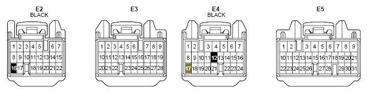
4. Disconnect the stock ECU. There are 4 plugs that go into the ECU. They can only go in their designated slot, but be sure you know which one is which. Here are the pin locations and colors of the plastic part of the connectors. This is also in the large comp diagram that you will see later:
5. CAREFULLY drill a hole through the side of the lower rubber grommet. Make sure you don’t drill into any wires. Do this from inside the storage bin area. You will need to pull all of the wires from the LC-1 through this hole. It doesn’t need to be huge, but it must be able to accommodate that. You can use an exacto knife to widen the hole if necessary.
6. First, pull the colored wires through the hole. I say pull because you’ll need to be cleaver and put something solid through the hole (like a fish tape) and attach the wires to it and pull that back through. This may take some time. Next plug the terminator into one of the 2 serial connections on the LC-1 and push that through the hole. Once through, remove the terminator and put it on the other one and push it through. You can leave the terminator in the “IN” connector as that’s where it will stay later. Make sure you really push it in good.
7. Pull the slack through the hole in the grommet so that your LC-1 controller is in the position you want and there is no excess slack in the wires in the engine bay. Also, make sure that the wires aren’t laying on anything that will be hot or possibly melt the wires.
8. Secure the LC-1 controller and wires to your mounting location. If you’re putting it where I did, then zip ties is all that’s needed. If you’re putting it somewhere else, then just make sure it’s secure and won’t move around. *NOTE* Do not plug in the WB Sensor yet. Just make sure it will go into its location and connect to the LC-1.
9. Now that you have all the wires inside the storage bin area, it’s time for the scary part. You will be cutting 3 wires on your ECU harness and splicing into them. For all of your splicing, solder the connections and shrink-tube them. You don’t want some ghetto installation that may come loose! Connect and splice wires as listed below. Look at the diagram for more help:
a. Red -> 5Amp Inline Fuze -> E2-16 (Black)
b. Blue -> Chassis Ground
c. White -> Combine with f. Green -> E4-17 (Brown)
d. Yellow -> E4-12 (Black)
e. Brown -> FC-Box AN1
f. Green -> Combine with c. White -> FC-Box AN2
g. Black -> LED (Red) + Push Button (Black) -> Both to Chassis Ground
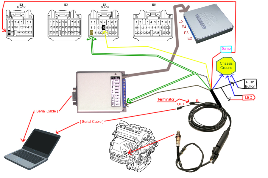
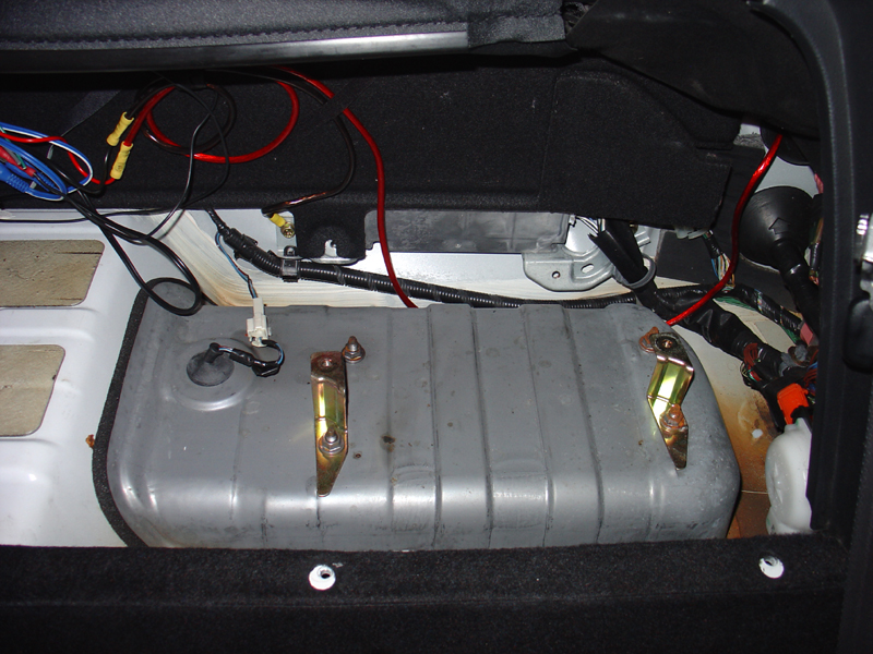
10. Connect FC-Box to PFC as shown above. And Mount PFC to top of gas tank using adhesive Velcro. Make sure that is won’t move around.
11. Plug the 4 wiring harness connectors into PFC. Refer to diagram for locations of each plug.
12. Make sure everything is hooked up and secure (The FC-Box can be somewhat loose if you’re going to mount it somewhere later once you’re finished. Just make sure that it’s mainly stationary.
13. Re-install Battery and connect the terminals.
14. Refer to the manual that comes with the LC-1 and perform the calibration of the LC-1. Then plug the sensor into the LC-1 controller and perform the open air calibration. Follow the instructions for these from the Innovate LC-1 Manual.
15. Unplug WB Sensor from the LC-1 and put the sensor into the stock O2 location. You will obviously need to remove the stock sensor to do this. Once it’s screwed in and all is good, re-connect the sensor plug into the LC-1.
16. Turn the key on and start the car. Let it run for a little bit and make sure that it runs. *NOTE* when I did this, it ran REALLY rich. Do this in a well ventilated area and turn on a fan or something. Anyway, make sure that it is all working before putting the other pieces back on.
17. Now you can just leave it all open like it is, or close it back up so that it looks nice. I chose to make it look nice. So… Put some sort of padding on top of the PFC (I used some drawer liner material). Re-install the storage bin plastic floor. Make sure that the FC-Box and the “OUT” plug from the LC-1 is accessible so you can plug your serial cables into them and unplug when needed. Put the remaining pieces back on.
18. Now if your laptop is normal and not incredibly old or basically if you don’t have 9-pin serial ports on it, then you will need to get a serial to USB converter. The one I used was from belkin. It costs about $50.00 locally at CompUSA. You will need 2 of them if you want to run the copilot with the WB02 reading as well as the PFC readings.
19. Plug them in and see what port they are emulating. Then follow the steps in Beanies thread for running the copilot and all that jazz. I wanted to get this topic posted so I may add his other information to here later on. I’m running short on time right now though.
20. Drive around with your friend operating the laptop and enjoy your new power and the incredibly cool and … well it’s just awesome … copilot software!